

[May-2026] Juniper JN0-364 Dumps - Secret To Pass in First Attempt
Juniper JN0-364 Exam Dumps [2026] Practice Valid Exam Dumps Question
NEW QUESTION # 33
Exhibit: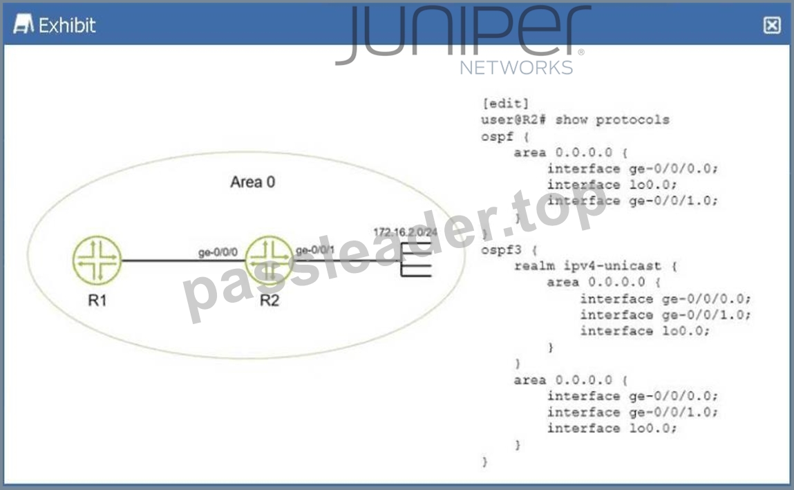
You have configured IPv4 and IPv6 in your network and all OSPF neighbors are established. You apply the configuration shown in the exhibit. Which statement is true in this scenario?
- A. There will only be an OSPFv2 entry in R1 for network 172.16.2.0/24.
- B. There will not be a route in R1 for network 172.16.2.0/24.
- C. There will be an OSPFv2 and OSPFv3 entry in R1 for network 172.16.2.0/24.
- D. There will only be an OSPFv3 entry in R1 for network 172.16.2.0/24.
Answer: C
Explanation:
In a Juniper Networks environment running Junos OS, understanding the interaction between different versions of OSPF is essential for multi-protocol environments.OSPFv2(defined in RFC 2328) is the standard protocol used for routing IPv4 unicast traffic.OSPFv3(defined in RFC 5340) was originally developed to support IPv6 routing. However, OSPFv3 was later extended via RFC 5838 to support multiple address families (AF), allowing it to carry IPv4 unicast, IPv4 multicast, and other address types within a single OSPF instance.
According to Juniper technical documentation, Junos OS implements this multi-AF support in OSPFv3 through the use ofrealms. When the realm ipv4-unicast statement is configured under the [edit protocols ospf3] hierarchy, the OSPFv3 process becomes capable of calculating and advertising IPv4 routes.
In the provided exhibit, routerR2has a dual-protocol configuration. First, it is running standard OSPFv2, with the ge-0/0/1.0 interface (which is directly connected to the 172.16.2.0/24 network) participating in Area 0.
This ensures that the prefix is advertised as a standard IPv4 LSA to its neighbor,R1. Second, R2 is running OSPFv3 with the realm ipv4-unicast specifically enabled on that same ge-0/0/1.0 interface. Because of this realm, OSPFv3 also treats the 172.16.2.0/24 prefix as a reachable IPv4 destination and advertises it to R1 as an OSPFv3 IPv4-unicast LSA.
As a result, whenR1(which is also running both protocols) receives these routing updates, it will see the same destination prefix advertised by two different protocols. Its routing table (inet.0) will contain one entry learned from the OSPFv2 process and a second, separate entry learned from the OSPFv3 process. While the Junos Routing Engine will ultimately select one as the "active" route based on route preference (both protocols have a default preference of 10), both entries will technically exist within the Routing Information Base (RIB). This confirms that statementBis the correct description of the operational state of the network.
=========
NEW QUESTION # 34
Exhibit:
user@Router-1> show route 172.24/16
inet.0: 9 destinations, 9 routes (9 active, 0 holddown, 0 hidden)
+ = Active Route, - = Last Active, * = Both
...
172.24.0.0/24 *[OSPF/150] 01:31:31, metric 0, tag 0
> to 172.20.0.2 via ge-0/0/2.0
to 172.20.1.2 via ge-0/0/3.0
user@Router-1> show route forwarding-table
Routing table: default.inet
Internet:
Destination Type RtRef Next hop Type Index NhRef Netif
...
172.24.0.0/24 user 0
172.20.0.2 ucst 551 2 ge-0/0/2.0
172.20.1.2 ucst 552 2 ge-0/0/3.0
Referring to the exhibit, which two statements are true? (Choose two.)
- A. The router is performing default route load-balancing behavior.
- B. The default route load-balancing behavior of this router has been modified.
- C. This router will choose both next hops in the routing table.
- D. This router will only choose the next hop with a > next to it in the routing table.
Answer: B,C
Explanation:
In Junos OS, understanding the distinction between theRouting Information Base (RIB)and theForwarding Information Base (FIB)is fundamental to analyzing traffic patterns and load-balancing behavior. The RIB (show route) contains all prefixes learned via various protocols, while the FIB (show route forwarding-table) contains only the active next-hops that are actually programmed into the Packet Forwarding Engine (PFE).
According to Juniper Networks technical documentation, the default behavior for Junos OS when encounteringEqual-Cost Multipath (ECMP)routes is to select only a single next-hop from the available candidates in the RIB and install that single path into the FIB. In a default state, even if the show route output displays multiple next-hops for a destination like 172.24.0.0/24, only one would have the active route symbol (
>) and only that one would appear in the forwarding table.
In the provided exhibit, the show route output shows two next-hops for 172.24.0.0/24, but only the first one (172.20.0.2) is marked with the>symbol as the active selection. However, the subsequent show route forwarding-table output reveals thatboth next-hops(172.20.0.2 and 172.20.1.2) are currently present in the forwarding table for that same destination. This discrepancy indicates that thedefault load-balancing behavior has been modified (Option B). This modification is typically achieved by creating a routing policy with the action then load-balance per-packet (which actually results in flow-based load balancing) and applying it to the forwarding table via the export statement under [edit routing-options forwarding-table].
Because the forwarding table now contains both next-hops, the router is no longer restricted to a single path.
Therefore, therouter will choose both next-hops in the routing table (Option D)for packet forwarding, distributing flows across the two available Gigabit Ethernet interfaces (ge-0/0/2.0 and ge-0/0/3.0). This ensures higher utilized bandwidth and provides redundancy at the data plane level.
NEW QUESTION # 35
Exhibit: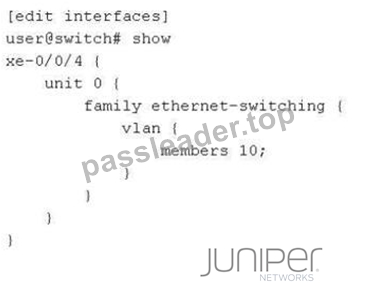
on a Juniper switch. It shows interfacexe-0/0/4withunit 0andfamily ethernet-switching. Under vlan, it lists members 10;`] Referring to the exhibit, which two statements are true? (Choose two.)
- A. The interface receives untagged traffic.
- B. The interface is a member of the VLAN named 10.
- C. The interface is a part of a VLAN that uses VLAN ID 10.
- D. The interface receives tagged traffic.
Answer: A,B
Explanation:
In Junos OS for switching platforms, an interface is configured for Layer 2 bridging under thefamily ethernet- switchinghierarchy. The way an interface handles VLAN traffic depends on its port mode:accessortrunk.
According to Juniper Networks technical documentation, when an interface is configured simply with members <vlan-name/id>, it defaults to anaccess port. In an access port configuration:
* The port is a member of only a single VLAN.
* The portreceives and sends untagged traffic (Option C). Any untagged frame arriving at this interface is implicitly associated with the configured VLAN member.
* The interface does not expect or process 802.1Q tags in incoming frames.
In the exhibit, interface xe-0/0/4 has members 10;. In Junos, the members statement can reference either a VLAN nameor aVLAN ID. However, when the configuration is shown as members 10; without further context of the specific ID mapping, the most precise interpretation of the CLI output provided is thatthe interface is a member of the VLAN named 10 (Option D). While "10" could be the numerical ID, Junos primarily maps members by their defined administrative name.
Why other options are incorrect:
* Option A:Access ports do not receive tagged traffic; only trunk ports (which require the port-mode trunk and vlan members [ ... ] statements) are designed to process tagged frames.
* Option B:While the VLAN named 10likelyhas a VLAN ID of 10, the exhibit does not explicitly confirm the ID mapping. In Junos, a VLAN named "10" could technically have a different tag ID (e.g., VLAN "Office" with ID 10). Option D is the more accurate direct reading of the displayed member configuration.
NEW QUESTION # 36
Exhibit:
user@R1> show route 10.16.2.0/23 exact detail
inet.0: 12 destinations, 12 routes (11 active, 0 holddown, 1 hidden)
10.16.2.0/23 (1 entry, 1 announced)
*Aggregate Preference: 130
Next hop type: Reject
Address: 0x8f3fd44
Next-hop reference count: 2
State: <Active Int Ext>
Age: 1:39:21
Task: Aggregate
Announcement bits (1): 0-KRT
AS path: I (LocalAgg)
Flags: Depth: 0 Active
AS path list:
AS path: I Refcount: 2
Contributing Routes (2):
10.16.2.0/24 proto Direct
10.16.3.0/24 proto Direct
Which destination IP address will be matched by the aggregate route shown in the exhibit?
- A. packets destined to 10.16.0.4
- B. packets destined to 10.16.4.183
- C. packets destined to 10.16.3.79
- D. packets destined to 10.16.1.214
Answer: C
Explanation:
In the Juniper Networks Junos operating system,aggregate routesare used to represent a group of more specific routes with a single, shorter prefix. This technique is essential for reducing the size of routing tables and minimizing the volume of routing updates sent to neighbors. According to Juniper technical documentation, for a destination IP address to "match" a specific route, it must fall within the range defined by the network address and its associated CIDR mask.
The provided exhibit shows a detailed lookup for the aggregate route$10.16.2.0/23$. To determine the range of IP addresses covered by a $/23$ mask, we examine the binary representation of the third octet. A $/23$ mask means the first 23 bits are fixed. For the address $10.16.2.0$:
* The first two octets ($10.16$) are fixed.
* The third octet ($2$) is $00000010$ in binary.
* The 23rd bit is the second-to-last bit of this octet.
* The $/23$ range allows the 24th bit (the last bit of the third octet) and all 8 bits of the fourth octet to vary.
This results in a range where the third octet can be either $2$ ($00000010$) or $3$ ($00000011$). Therefore, the aggregate route $10.16.2.0/23$ covers all IP addresses from$10.16.2.0$ to $10.16.3.255$. The exhibit further confirms this by listing the "Contributing Routes": $10.16.2.0/24$ and $10.16.3.0/24$.
Analyzing the provided options against this range:
* 10.16.3.79 (Option A):This address falls squarely within the $10.16.2.0$ to $10.16.3.255$ range.
* 10.16.0.4 (Option B):This address falls in the $10.16.0.0/23$ range ($0.0$ to $1.255$).
* 10.16.4.183 (Option C):This address falls in the $10.16.4.0/23$ range ($4.0$ to $5.255$).
* 10.16.1.214 (Option D):This address also falls in the $10.16.0.0/23$ range.
Consequently,10.16.3.79is the only destination listed that matches the aggregate route shown. It is also important to note theNext hop type: Rejectin the exhibit; this means that if a packet matches the aggregate but does not match any of the more specific contributing routes, the router will drop the packet and send an ICMP unreachable message to the source.
NEW QUESTION # 37
What happens if an IS-IS router receives a link-state PDU with a higher sequence number than the one in its database?
- A. It resets the adjacency with the source of the link-state PDU.
- B. It ignores the link-state PDU.
- C. It updates its database and floods the link-state PDU.
- D. It sends a CSNP to request confirmation from the source of the link-state PDU.
Answer: C
Explanation:
IS-IS is a link-state protocol that relies on the rapid and consistent flooding ofLink-State PDUs (LSPs)to ensure that every router in an area has an identical view of the topology. To manage the "freshness" of information, IS-IS uses aSequence Number-a 32-bit unsigned integer that increments every time the originating router makes a change to its LSP.
According to Juniper Networks technical documentation, when a router receives an LSP, it performs a comparison between the received LSP and the version it currently holds in itsLink-State Database (LSDB).
If the received LSP has ahigher sequence number, the router concludes that this is "newer" and more accurate information. The router will then perform two immediate actions:
* Update:It replaces the older LSP in its LSDB with the newly received version.
* Flood:It propagates the new LSP to all other neighbors (except the one that sent it) to ensure the entire area converges on the new data.
If the sequence numbers were equal, the router would ignore the incoming PDU as it already has the information. If the received sequence number werelower, the router would conclude its own database is more recent and would actually send its own "newer" version back to the neighbor to bring them up to date (a process called "poisoning" or refreshing the neighbor).Complete Sequence Number PDUs (CSNPs)(Option C) are used during initial database synchronization or periodic checks on broadcast links, but the primary response to a "newer" LSP is immediate database update and flooding.
NEW QUESTION # 38
Exhibit:
user@R10> show configuration protocols isis
interface ge-0/0/1.0 {
point-to-point;
}
interface ge-0/0/2.0 {
point-to-point;
}
interface lo0.0;
source-packet-routing {
srgb start-label 300000 index-range 10000;
}
level 1 disable;
level 2 wide-metrics-only;
reference-bandwidth 100g;
You have a network of ten routers that have all been configured with an identical SRGB. The exhibit shows the IS-IS configuration from a router called R10. The other nine routers do not yet have an IPv4 shortest-path SR-MPLS LSP to this router. Which missing part of the configuration must you add on R10 to solve this problem?
- A. R10 must be configured with explicit IPv4 adjacency SID.
- B. R10 must tag its internal IPv4 BGP prefixes with a BGP prefix SID.
- C. R10 must be configured with an explicit IPv4 node SID.
- D. R10 must be configured with an explicit binding SID.
Answer: C
Explanation:
In aSegment Routing (SR-MPLS)architecture using IS-IS as the control plane, routers exchange labels (segments) to build Label-Switched Paths (LSPs) without the need for traditional signaling protocols like LDP or RSVP. According to Juniper Networks technical documentation, for a router to be reachable via a shortest- path LSP from other nodes in the network, it must advertise aPrefix Segment Identifier (Prefix SID).
A specific type of Prefix SID is theNode SID, which is assigned to a loopback address (typically lo0.0) to uniquely identify the router within the SR domain. In the provided exhibit, routerR10has been configured with aSegment Routing Global Block (SRGB)starting at label 300000. This configuration tells the router which label range to use for global segments, but it does not automatically assign a label to its own loopback interface.
Without aNode SIDconfiguration, R10 is not telling its neighbors which specific index or label within that SRGB corresponds to its own address. Consequently, the other nine routers in the IS-IS area can calculate the shortest path to R10 using standard SPF, but they cannot perform the "label-binding" necessary to push an SR- MPLS label onto the packets.
To solve this, a Node SID must be explicitly configured under the loopback interface within the IS-IS protocol hierarchy, such as:
set protocols isis interface lo0.0 level 2 ipv4-node-sid index <value>
Analysis of incorrect options:
* Binding SID (Option A):This is used to encapsulate or steer traffic into a specific policy or tunnel (like a TE-LSP) and is not required for basic shortest-path reachability.
* Adjacency SID (Option B):These are generated automatically by Junos for each link and represent a specific local hop; they are not used for global "shortest-path" forwarding to a distant node.
* BGP Prefix SID (Option C):This is used for BGP Egress Peer Engineering (EPE) or prefix advertisement via BGP, which is not relevant for building the underlying IS-IS SR-MPLS transport.
Therefore, configuring anexplicit IPv4 node SIDis the mandatory step to enable the rest of the network to build a shortest-path SR-LSP toward R10.
NEW QUESTION # 39
What prevents routing loops in a single-area OSPF network?
- A. The Bellman-Ford algorithm
- B. The Dijkstra algorithm
- C. Forwarding policies
- D. Routing policies
Answer: B
Explanation:
In OSPF, loop prevention within a single area is achieved through the fundamental nature of its link-state architecture. Unlike distance-vector protocols that rely on "routing by rumor," OSPF ensures that every router within an area maintains an identicalLink-State Database (LSDB). This database acts as a complete map of the network topology.
Once the LSDB is synchronized, each router independently executes theShortest Path First (SPF) algorithm
, which is formally known as theDijkstra algorithm. This mathematical process treats the local router as the
"root" of a tree and calculates the shortest path to every other node (router) and prefix in the area based on the cumulative interface costs. Because every router uses the same synchronized map (the LSDB) and the same deterministic algorithm, they all arrive at a consistent, loop-free view of the best paths.
According to Juniper Networks technical documentation, the Dijkstra algorithm is superior to theBellman- Ford algorithm(used by distance-vector protocols like RIP) in this regard. Bellman-Ford is susceptible to
"count-to-infinity" problems and loops because routers only know the distance and direction to a destination provided by their neighbors, rather than the full topology. In OSPF, even if a link fails, the updated Link-State Advertisement (LSA) is flooded rapidly, and the Dijkstra algorithm is re-run to find a new loop-free path.
Routing policies(Option B) are used to manipulate path selection or filter routes but are not the primary mechanism for fundamental loop prevention in OSPF. Similarly,forwarding policies(Option D) govern how traffic is handled at the data plane level rather than determining the control plane's loop-free topology.
NEW QUESTION # 40
Exhibit:
Referring to the exhibit, why is the ge-0/0/0.0 interface shown as belonging to Level 3?
- A. This interface connects to a super spine.
- B. This interface is configured as a broadcast interface that has three adjacencies with other routers on the shared LAN.
- C. This interface is configured as a broadcast interface, that uses Level 3 as shorthand for both Level 1 and Level 2.
- D. This interface is configured as a point-to-point interface, that uses Level 3 as shorthand for both Level 1 and Level 2.
Answer: D
Explanation:
In theIS-IS (Intermediate System to Intermediate System)protocol as implemented in Junos OS, the output of operational commands uses specific numerical representations to denote the hierarchy levels of a neighbor adjacency. Understanding these values is crucial for troubleshooting peering relationships in a multi-level IS- IS network.
According to Juniper Networks technical documentation, the show isis adjacency command displays the status of the neighbors. The "L" column indicates the level of the adjacency:
* Level 1:Indicates the adjacency is strictly for intra-area routing.
* Level 2:Indicates the adjacency is strictly for backbone/inter-area routing.
* Level 3:This is ashorthand representationused by Junos to indicate that a single adjacency has been established forboth Level 1 and Level 2 simultaneously.
The critical distinction in this question lies in the interface type. On abroadcast interface(such as standard Ethernet), IS-IS typically establishes and maintains separate adjacencies for Level 1 and Level 2. In the CLI output for a broadcast link, you would generally see two separate lines for the same neighbor-one for Level
1 and one for Level 2.
However, on apoint-to-point (P2P)interface, IS-IS can negotiate both levels within a single adjacency. When this occurs, Junos consolidates the output into a single entry and usesLevel 3to signify that the adjacency is functional for both levels. Since the exhibit shows ge-0/0/0.0 as Level 3, it confirms that the link is configured with a point-to-point encapsulation (either natively or via the interface-type p2p command) and is acting as a Level 1/2 adjacency.
Option B is incorrect as the number "3" refers to protocol levels, not the count of neighbors. Option C is a reference to data center architectures that does not influence IS-IS level nomenclature. Option D is incorrect because, as noted, broadcast interfaces display these levels separately rather than using the Level 3 shorthand.
NEW QUESTION # 41
Exhibit: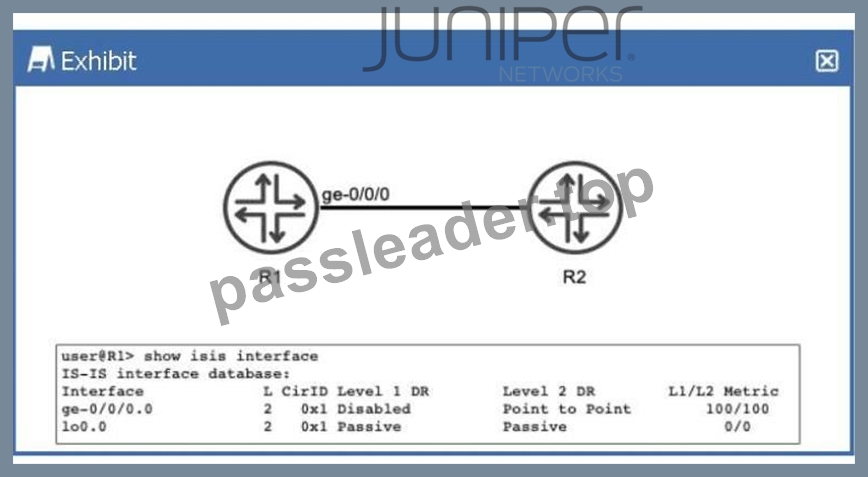
Referring to the exhibit, R1 and R2 are configured to run IS-IS. The IS-IS adjacency between R1 and R2 is up. What does the output of the show isis interface command tell you about R1?
- A. R1 only forms a Level 2 adjacency with R2.
- B. R1 advertises a Level 1 metric of 100 and a Level 2 metric of 100 toward R2 in its link-state PDU.
- C. R1 sends Level 1 hello PDUs to R2.
- D. R1 is not configured to use wide metrics.
Answer: A
Explanation:
In theIS-IS (Intermediate System to Intermediate System)protocol as implemented in Junos OS, routers can operate at two hierarchical levels:Level 1 (L1)for intra-area routing andLevel 2 (L2)for inter-area backbone routing. By default, a Juniper router and its interfaces are configured to act asLevel 1/2, meaning they will attempt to form adjacencies at both levels simultaneously.
According to Juniper Networks technical documentation, the show isis interface command provides a granular view of how the protocol is interacting with specific local links. In the provided exhibit, we must examine the L (Level)column and theDR (Designated Router)status columns to understand R1's operational state.
* Level Configuration:Under the L column for both the physical interface ge-0/0/0.0 and the loopback lo0.0, the value is strictly2. This indicates that these interfaces have been explicitly configured to operate only at Level 2.
* Adjacency Capabilities:For the interface ge-0/0/0.0, the Level 1 DR field is marked asDisabled. This confirms that R1 is not participating in Level 1 operations on this link; it will not transmit Level 1 Hello PDUs, nor will it listen for them. Consequently, R1 is incapable of forming a Level 1 adjacency with R2 on this segment.
* Metric Implications:The exhibit shows an L1/L2 Metric of100/100. In Junos, "narrow" metrics (the default) are limited to a maximum value of 63 per interface. A metric of 100 indicates thatwide metrics (wide-metrics-only) have been enabled. Therefore, option A is incorrect because the routerisusing wide metrics.
Since the prompt states the adjacency is "up," and the interface is restricted to Level 2, we can conclude that R1 only forms a Level 2 adjacency with R2 (Option B). Even though an L1 metric of 100 is displayed in the table as a configured value, it is not actually "advertised" in a Link-State PDU because the Level 1 protocol is disabled on that interface.
NEW QUESTION # 42
You are configuring BGP on a Juniper router to peer with an external provider. After committing the configuration, the BGP session remains in the Idle state. Which configuration issue would prevent the BGP session from progressing beyond the Idle state?
- A. The BGP group type is set to internal instead of external.
- B. The peer is configured with a different router ID.
- C. The local AS number is higher than the peer's AS number.
- D. The peer IP address is unreachable.
Answer: D
Explanation:
In the BGP finite state machine, theIdlestate is the "stop" or "start" point of the protocol. When a session is stuck in Idle, it means the BGP process is either administratively disabled or, more commonly, is unable to initiate the underlying TCP connection required for BGP.
According to Juniper Networks Service Provider documentation, the most common reason for a BGP session to remain in Idle is a lack ofrouting reachability. For BGP to move to theConnectstate, the Junos kernel must have a route to the IP address specified in the neighbor statement. If thepeer IP address is unreachable (Option A)-meaning there is no route in inet.0 (via OSPF, IS-IS, or static)-the router cannot initiate the TCP three-way handshake on port 179. Consequently, the state machine will never progress.
Analysis of incorrect options:
* Option B:BGP does not care if the local AS is higher or lower than the peer's; it only cares if they match the configuration. AS numbers are identifiers, not priorities.
* Option C:A mismatchedRouter IDdoes not prevent a session from leaving the Idle state. It would typically cause the session to reach theOpenConfirmstate, and then fail with a "Notification" message due to a collision or identification error.
* Option D:While a mismatchedgroup type(internal vs. external) will cause the session to fail, it usually fails during theOpenmessage exchange (OpenSent state) because the AS numbers provided will not match the expected peer type (IBGP vs. EBGP).
Only the lack of a path to the neighbor (reachability) keeps the session at the very beginning of the process:
theIdlestate.
NEW QUESTION # 43 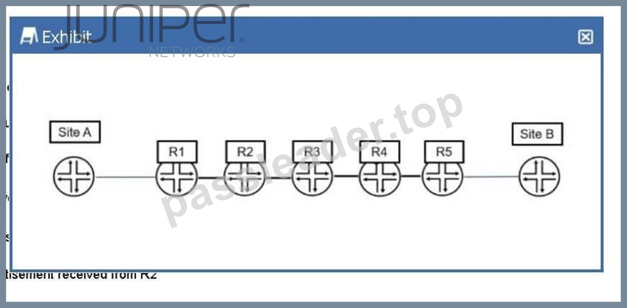
In the exhibit, Site A is sending traffic to Site B. R1 adds MPLS label 7166 to direct the traffic to R5. Which two criteria did R1 use to determine which label number to add to the traffic? (Choose two.)
- A. a label number advertisement received from R2
- B. the source address of the traffic
- C. a label number received from R5
- D. the destination address of the traffic
Answer: A,D
Explanation:
In a Juniper Networks MPLS environment, the process by which a router determines how to forward traffic involves both the control plane and the data plane. When R1 (acting as an Ingress Label Edge Router, or LER) receives an IP packet from Site A destined for Site B, it must perform a lookup to decide whether to forward the packet via standard IP routing or via an MPLS Label Switched Path (LSP).
The first criterion R1 uses is thedestination address of the traffic(Option C). Upon receiving the native IP packet, R1 looks up the destination IP in its routing table (typically inet.0). If the destination matches a prefix that is associated with an LSP-such as the loopback address of R5 or a prefix reachable via R5-the router identifies the appropriate Forwarding Equivalence Class (FEC). The FEC essentially groups packets that should be forwarded in the same manner over the same path. Without identifying the destination, the router cannot map the traffic to the correct MPLS tunnel.
The second criterion is thelabel number advertisement received from R2(Option D). MPLS relies on downstream label allocation. In this topology, R2 is the immediate downstream "next hop" for R1 on the path to Site B. For the LSP to be established, R2 must signal a label to R1 using a protocol like LDP (Label Distribution Protocol) or RSVP (Resource Reservation Protocol). This label (in this case, 7166) tells R1: "If you want to send traffic to the destination associated with this LSP, wrap it in this specific label so I know how to process it." R1 does not use the source address (Option A) for standard label mapping, nor does it receive the label directly from R5 (Option B) in a hop-by-hop signaling model; it must use the label provided by its direct neighbor, R2. Therefore, by combining the destination IP (to find the path) and the label provided by the next hop (to encapsulate the packet), R1 successfully directs the traffic through the MPLS core.
NEW QUESTION # 44
Which two statements about graceful restart are correct? (Choose two.)
- A. Graceful restart uses nonstop bridging for forwarding operations.
- B. Graceful restart helper mode is enabled by default.
- C. Graceful restart requires that GRES be enabled.
- D. Graceful restart restarting router mode is not enabled by default.
Answer: B,D
Explanation:
Graceful Restart (GR)is a high-availability mechanism designed to minimize the impact of a routing protocol process (rpd) restart or a Routing Engine (RE) switchover. It allows a router to continue forwarding traffic while the control plane is recovering, provided that the data plane (Packet Forwarding Engine) remains intact.
According to Juniper Networks documentation, Graceful Restart operates in two distinct roles:
* Restarting Mode:This is the role of the router that is actually undergoing the restart. In Junos OS, this mode isnot enabled by default (Option A). An administrator must explicitly configure graceful-restart under the [edit routing-options] hierarchy to allow the router to signal its neighbors that it is attempting a graceful recovery.
* Helper Mode:This is the role of the neighboring routers. When a neighbor sees a router restart, if it is in "helper mode," it will continue to forward traffic toward the restarting router and will not flush the associated routes from its forwarding table for a specified period. In Junos,helper mode is enabled by default (Option B)for most protocols (OSPF, BGP, IS-IS). This means that even if you haven't configured GR on your own router, it will automatically assist its neighbors if they perform a graceful restart.
Why other options are incorrect:
* Option C:WhileGRES (Graceful Routing Engine Switchover)is often usedwithGraceful Restart to handle hardware-level RE failures, they are independent features. GR can function during a simple software process restart without dual REs or GRES.
* Option D:Nonstop Bridging (NSB)is a separate high-availability feature for Layer 2 protocols (like STP). While it shares a similar goal, Graceful Restart is specifically a Layer 3 protocol mechanism (Layer 2 does not use "helper" routers in the same way).
NEW QUESTION # 45
You are using EBGP to connect to two upstream peers in the same AS. You want to make one of the links less preferred for traffic entering your network from the peer's AS. Which feature should you use to achieve this goal?
- A. AS-path prepending
- B. a route reflector
- C. origin code
- D. local preference
Answer: A
Explanation:
In the world of BGP, controllinginbound traffic(traffic entering your network) is significantly more challenging than controlling outbound traffic because it requires influencing a decision made by an external Autonomous System (AS). According to Juniper Networks documentation, when you have multiple links to the same AS or even different ASes, the BGP path selection process is used by the upstream neighbor to decide which path to take to reach your prefixes.
AS-Path Prependingis the standard technique used to make a path appear less attractive to external peers. By artificially lengthening the AS_PATH attribute on the BGP advertisements sent over a specific link, you exploit the BGP best-path algorithm rule that prefers a shorter AS path. When you prepend your own AS number multiple times to the update sent to the "less preferred" peer, that peer's BGP routers will see a longer path compared to the alternative link and will naturally prefer the shorter, unprepended route.
It is important to distinguish why other options are incorrect for this specific goal:
* Local Preference (Option D):This is a well-known discretionary attribute used to influenceoutbound traffic. It is not advertised to EBGP peers; therefore, your upstream neighbor cannot see your local preference settings.
* Origin Code (Option B):While the origin code (IGP, EGP, or Incomplete) is a tie-breaker in the selection process, it is rarely used for traffic engineering and lacks the granular control provided by prepending.
* Route Reflector (Option A):This is an Internal BGP (IBGP) scaling mechanism used to reduce the need for a full mesh of peers within an AS; it does not directly influence external path selection by an upstream provider.
Junos OS allows you to easily implement prepending viarouting policiesapplied as an "export" policy to the EBGP neighbor. By using the as-path-prepend action within a policy term, you can selectively degrade a path's attractiveness to manage your inbound bandwidth.
NEW QUESTION # 46
You are asked to add next-hop redundancy using VRRP for an IPv6 enabled service. The configured primary router must always be active when available, and the servers connected to the network must be able to ping their gateway. Which VRRP element is required to accomplish this requirement?
- A. The preempt parameter must be added to the VRRP configuration.
- B. The accept-data parameter must be added to the VRRP configuration.
- C. The backup router requires the track parameter to track the primary router's interface.
- D. Both routers running VRRP will require a static ARP entry to be configured for the VRRP VIP.
Answer: B
Explanation:
InVirtual Router Redundancy Protocol (VRRP), the primary goal is to provide a highly available default gateway for end hosts. However, there is a specific operational behavior in the VRRP standard (RFC 3768
/RFC 5798) regarding how the "Virtual Router" responds to traffic destined for its own Virtual IP (VIP).
According to Juniper Networks documentation, by default, a VRRP router that is in the Master state will only respond to packets destined for the VIP if that router is theIP Address Owner(meaning its physical interface IP matches the VIP). If the router is a "non-owner" (a common configuration in many networks), it will forward traffic on behalf of the VIP but will not respond to management traffic, such asICMP Echo Requests (Pings), directed at the VIP itself.
To satisfy the requirement that "servers connected to the network must be able to ping their gateway," the accept-data (Option D)parameter must be configured. In Junos OS, the accept-data statement allows the VRRP Master to respond to traffic destined for the virtual IP address even if it is not the address owner. This includes responding to Pings and allowing other management connections like SSH or Telnet to the VIP.
Regarding the other options:
* Preempt (Option B):While preempt is often used to ensure the primary router regains control, in Junos, a router with the highest priority (255) defaults to preemptive behavior, and accept-data is specifically what solves the "pinging the gateway" requirement.
* Track (Option A):Tracking is used for failover logic but doesn't affect the ability to ping the VIP.
* Static ARP (Option C):This is unnecessary as VRRP uses a virtual MAC address to ensure hosts can resolve the VIP via standard NDP (for IPv6) or ARP (for IPv4).
NEW QUESTION # 47
You are designing a high availability solution for a Juniper router with dual Routing Engines (RE). You want to ensure that the routing protocol state is preserved during an RE switchover. You have already enabled graceful Routing Engine switchover (GRES) and you want to avoid relying on helper routers to maintain the routing protocol state. In this scenario, which feature would accomplish this behavior?
- A. bidirectional forwarding detection
- B. non-stop active routing
- C. graceful restart
- D. non-stop active bridging
Answer: B
Explanation:
When designing High Availability (HA) for Juniper Service Provider routers, understanding the interaction between the control plane and data plane is vital. The user has already enabledGraceful Routing Engine Switchover (GRES), which synchronizes the interface and kernel state between the primary and backup Routing Engines (REs). However, GRES by itself does not preserve the routing protocol state (like OSPF adjacencies or BGP sessions).
To achieve the preservation of the routing protocol state without relying on external "helper" routers, you must implementNon-Stop Active Routing (NSR). According to Juniper Networks documentation, NSR uses the infrastructure provided by GRES to also synchronize the routing protocol process (rpd) information.
Under NSR, the backup RE maintains a "hot" standby state of all routing protocols. If the primary RE fails, the backup RE takes over immediately. Because it already possesses the full routing table and peer session states, the peering neighbors are unaware that a switchover occurred. No protocol adjacency resets occur, and traffic continues to flow uninterrupted.
It is crucial to differentiate NSR fromGraceful Restart (Option C). While Graceful Restart also aims to maintain traffic flow during a switchover, itdoesrequire help from neighboring routers (known as "helper mode"). If the neighbors do not support or are not configured for Graceful Restart, the sessions will drop.
Since the user explicitly stated they want to "avoid relying on helper routers," Graceful Restart is not the correct solution.
Non-stop Active Bridging (Option A)provides a similar "hitless" failover but specifically for Layer 2 environments (STP/VLANs) rather than Layer 3 routing protocols.BFD (Option B)is a failure detection protocol used to speed up convergence but does not preserve state during an RE failover; in fact, without NSR, BFD would likely trigger a faster teardown of the session during a switchover. Therefore,NSRis the only feature that meets the requirement for independent control-plane preservation.
NEW QUESTION # 48 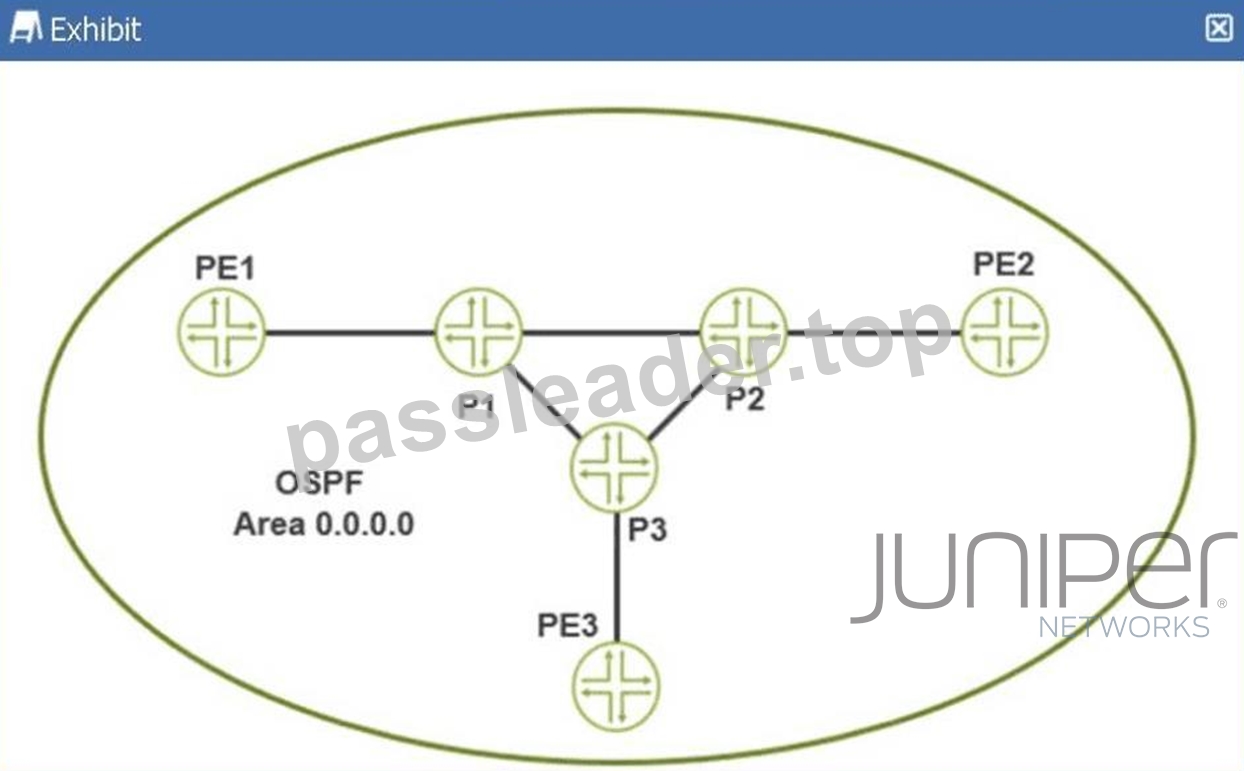
Referring to the exhibit, which protocol would automatically create a full mesh of label-switched paths between MPLS-enabled routers?
- A. RSVP
- B. BGP
- C. LDP
- D. BFD
Answer: C
Explanation:
In Juniper Networks Junos OS, theLabel Distribution Protocol (LDP)is specifically designed to automate the creation of Label Switched Paths (LSPs) based on the information provided by the underlying Interior Gateway Protocol (IGP), such as OSPF or IS-IS. When LDP is enabled on a set of interfaces within an OSPF area (as shown in the exhibit with Area 0.0.0.0), it automatically discovers neighbors and exchanges label mappings for all known unicast routes in the routing table.
The defining characteristic of LDP in this context is its "topology-driven" nature. Unlike RSVP (Resource Reservation Protocol), which typically requires the manual configuration of each LSP ingress point and destination, LDP follows the IGP's shortest path tree to automatically build afull meshof LSPs between all participating routers. This means that every Provider Edge (PE) and Provider (P) router in the exhibit-PE1, PE2, PE3, P1, P2, and P3-will establish label-switched connectivity to every other router without the administrator having to define individual tunnels.
LDP accomplishes this through a downstream-unsolicited label distribution mode by default in Junos. Each router assigns a local label for its loopback address and other prefixes and advertises these to its neighbors.
Because every router is performing this action for every reachable prefix in the OSPF domain, a complete fabric of label-switched paths is formed. While RSVP is more robust for traffic engineering and bandwidth reservation, LDP is the preferred protocol for creating a simple, scalable full mesh of LSPs for applications like Layer 3 VPNs or internal BGP tunneling where complex path manipulation is not required. BFD is a failure detection protocol, and BGP is used for service signaling, making LDP the only correct choice for automatic mesh creation.
NEW QUESTION # 49
Which IS-IS adjacency state indicates that hello packets have been exchanged but the adjacency is not yet fully established?
- A. up
- B. loading
- C. two-way
- D. initializing
Answer: D
Explanation:
In theIS-IS (Intermediate System to Intermediate System)protocol, the process of forming an adjacency between two neighbors follows a specific sequence of states. While OSPF uses states like "Init," "Two-Way," and "Full," IS-IS uses a slightly different nomenclature within its state machine.
According to Juniper Networks technical documentation, when a router first sends anIS-IS Hello (IIH) PDU and receives one back from a neighbor, but has not yet confirmed that the neighbor "sees" it back, the adjacency enters theInitializingstate. Specifically, on a point-to-point link, the state transitions fromDownto Initializingas soon as the first PDU is received. On a broadcast network (like Ethernet), the Initializing state indicates that the local router has received a Hello PDU from the neighbor, but the local router's own System ID is not yet listed in the neighbor's list of "seen" neighbors (the neighbor's Hello PDU does not yet contain the local router's MAC address).
The adjacency only moves to theUpstate (Option C) once bi-directional communication is confirmed- meaning both routers have seen each other's System IDs in the incoming Hello PDUs.
Why other options are incorrect:
* Loading (Option A):This is an OSPF state, not an IS-IS state. In IS-IS, database synchronization happens after the adjacency is Up.
* Two-Way (Option D):While functionally similar to the state IS-IS is achieving, "Two-Way" is the specific terminology for OSPF. In IS-IS, the intermediate step between knowing a neighbor exists and having a fully functional adjacency is strictly calledInitializing.
NEW QUESTION # 50
Exhibit: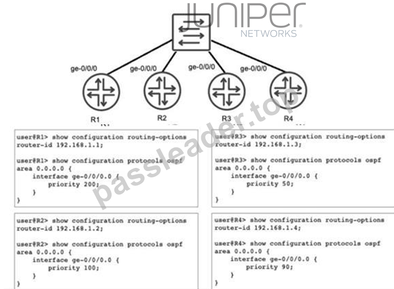
Referring to the exhibit, you have configured R1, R2, R3, and R4 to be a part of OSPF area 0 and you have connected them to a broadcast segment. Assuming all four routers come online within one minute of each other, which router becomes the DR and which router becomes the BDR?
- A. R1 is the DR and R2 is the BDR
- B. R4 is the DR and R1 is the BDR
- C. R1 is the DR and R4 is the BDR
- D. R4 is the DR and R3 is the BDR
Answer: A
Explanation:
In OSPF networks, when multiple routers are connected to a shared multi-access broadcast segment (like an Ethernet switch), they undergo an election process to select aDesignated Router (DR)and aBackup Designated Router (BDR). This mechanism is essential for reducing the number of adjacencies and limiting the volume of Link State Advertisement (LSA) flooding on the segment.
The OSPF election process follows a strict hierarchy based on the following criteria:
* Interface Priority:The router with the highest OSPF interface priority is elected as the DR. The router with the second-highest priority becomes the BDR. In Junos, the default priority is 128, but it can be manually configured between 0 and 255.
* Router ID:If there is a tie in priority, the router with the numerically highest Router ID (RID) wins the election.
Analyzing the configuration provided in the exhibit:
* R1:Priority 200, Router-ID 192.168.1.1
* R2:Priority 100, Router-ID 192.168.1.2
* R3:Priority 50, Router-ID 192.168.1.3
* R4:Priority 90, Router-ID 192.168.1.4
Comparing the priority values,R1 has the highest priority (200)and therefore becomes theDR. The next highest priority value among the remaining routers is100, which belongs to R2, making it theBDR. Although R4 has a higher Router ID than R2, the priority value is evaluated first and takes precedence.
Since all routers came online within a short window (one minute), they participate in the same election cycle, ensuring the configured priorities dictate the outcome rather than "first-come, first-served" preemption behavior common in OSPF once a DR is already established.
NEW QUESTION # 51
Which two protocols would be used for dynamic routing in IPv6 environments? (Choose two.)
- A. IS-IS
- B. BGP
- C. IGMP
- D. OSPFv2
Answer: A,B
Explanation:
The transition to IPv6 requires routing protocols that are capable of carrying 128-bit address information.
Juniper Networks Junos OS supports several "IPv6-ready" protocols for dynamic routing.
1. IS-IS (Option B):
As discussed in previous questions,IS-ISis inherently extensible due to its use ofTLVs (Type, Length, Value)
. To support IPv6, the protocol did not need a major rewrite; instead, new TLVs (such as TLV 236 for IPv6 reachability and TLV 232 for IPv6 interface addresses) were added. A single IS-IS process in Junos can simultaneously carry both IPv4 and IPv6 routing information, making it a highly efficient choice for "dual- stack" service provider backbones.
2. BGP (Option D):
BGP was updated to support multiple protocols throughMultiprotocol Extensions (MP-BGP), defined in RFC 4760. By usingAddress Family Identifiers (AFI)andSubsequent Address Family Identifiers (SAFI), a single BGP session can exchange NLRI (Network Layer Reachability Information) for IPv4 unicast, IPv6 unicast, and even VPNv4/VPNv6 routes. In Junos, this is configured under the family inet6 unicast hierarchy within the BGP protocols configuration.
Why other options are incorrect:
* IGMP (Option A):This is a management protocol for IPv4 multicast (Internet Group Management Protocol). Its IPv6 equivalent isMLD (Multicast Listener Discovery).
* OSPFv2 (Option C):OSPF version 2 is strictly for IPv4. To run OSPF in an IPv6 environment,OSPFv3 must be used, as it was specifically redesigned to handle the IPv6 address space and link-local communication.
NEW QUESTION # 52
You are asked to configure interfaces on Juniper devices to support dual VLAN tags. In this scenario, which two interface statements would accomplish this task? (Choose two.)
- A. flexible-vlan-tagging
- B. vlan-tagging
- C. gigether-options
- D. stacked-vlan-tagging
Answer: A,D
Explanation:
To supportdual VLAN tagging(often referred to as Q-in-Q or 802.1ad), a Juniper interface must be configured to process more than one 802.1Q header. In Junos OS, this is handled at the physical interface level ([edit interfaces <interface-name>]).
According to Juniper Service Provider documents, two primary configuration statements enable this capability:
* stacked-vlan-tagging (Option D):This is the traditional command used to enable an interface to accept frames with two VLAN tags. When this is enabled, the router expects an outer "service" tag and an inner "customer" tag. This is specifically used in provider edge scenarios where a service provider is tunneling multiple customer VLANs.
* flexible-vlan-tagging (Option A):This is a more modern and versatile command. It allows the interface to support a mix of different encapsulation types across different logical units. For example, with flexible-vlan-tagging, you can have one logical unit (unit 10) doing standard single-tagging and another logical unit (unit 20) doing dual-tagging (vlan-tags outer X inner Y). This is the preferred method on newer hardware (like the MX Series) because it provides the highest level of configuration flexibility.
Vlan-tagging (Option C)only enables the interface to support a single 802.1Q tag, andgigether-options (Option B)contains physical-layer settings like auto-negotiation or flow control, which do not influence VLAN encapsulation. Therefore, A and D are the correct mechanisms for enabling dual-tag support.
NEW QUESTION # 53
......
JN0-364 Exam Dumps PDF Guaranteed Success with Accurate & Updated Questions: https://examcertify.passleader.top/Juniper/JN0-364-exam-braindumps.html